Besides its primary application in the common radio set, the magic eye was used for other applications as well, primarily testing devices or electronic measuring devices. During the late 1930's and through the 40's, the magic eye tube became an attractive option for inventors over the more expensive D'Arsonval meter movement. General Motors, RCA, General Electric, Raytheon, and other corporations designed and patented many pieces of machinery and equipment that used the magic eye tube. Much of the military or commercial pieces of equipment were seldom seen by the general public. On occasion, I have seen articles in electronics hobby magazines that have projects which use a magic eye tube. Among these have been tape recording strength indicators, dwell meters, inductance bridges, and even an electronic exposure meter (how anyone could possibly have one of these things glowing away in their darkroom and not have it affect the picture developing process is beyond me!). I have shown a few instruments that deserve attention.
|
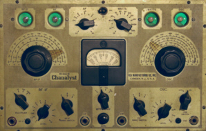
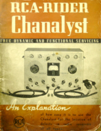
The RCA-Rider Chanalyst (left) was one of the first pieces of test equipment to use the magic eye tube, or, tubes, as there were four of
them. The Chanalyst debuted in 1938, and was the radio serviceman's dream. Each of the four tubes had a function of test for the common receiver: The RF (radio frequency) and IF
(intermediate frequency stage, the AF (audio) stage, the local oscillator, and a test for power consumption (wattmeter). The manual for the Chanalyst (center) not only provides instructions for use of the actual instrument, but also
gives great tips for diagnosing and repairing sets! I could receive navigation beacons below 450khz when I connected the Chanalyst IF test stage to a longwire antenna. |
|
Most of the capacitance bridges and capacitor testers made before solid state instruments employed a magic eye tube as a null indicator, even if there was an analog meter included with the test apparatus. The main advantage of having the magic eye as the null indicator in a bridge circuit is that a higly unbalanced bridge will drive the tube into cutoff, whereas a D'Arsonval meter movement requires a sensitivity adjustment and could be easily damaged by an inexperienced operator. |
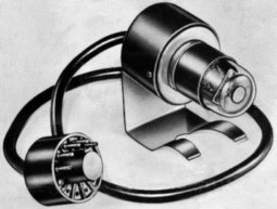
The "Eye Chek" by Hickok is a neat little instrument that you plug into the socket of a television picture tube. The tube used is a 6AF6. The checks accomplished are: filament voltage, anode voltage, intensity or brightness control, contrast control, and the prsence of video from the detector stage. Naturally, if the filament voltage and anode voltage are present, the eye will become illuminated. With the presence of video from the detector stage, one shadow of the eye will flutter. The amount of flutter should change as the contrast control is turned. The other shadow should open and close as the brightness control is turned. |
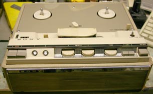
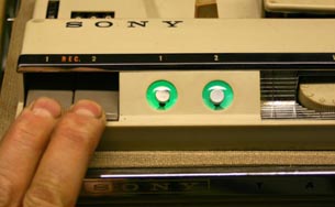
The magic eye tube was used extensively as a recording level indicator. Record lathes, wire recorders, and reel to reel tape recorders often utilized the magic eye tube well into the 1970s. Typically, the user of the recording device adjusts the recording level in such a manner that the shadow closes as much as possible without overlapping. This intuitive operation makes the magic eye tube exceptional for this purpose.
|
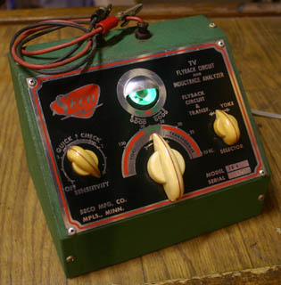
Here are a couple of uncommon devices utilizing the magic eye tube. Seco manufactured test equipment that utilized the magic eye tube and are best known for their tube testers. They did make other test equipment which also used the magic eye such as this flyback circuit and inductance analyzer used for television servicing (left). It has a very nicely designed slanted cabinet.
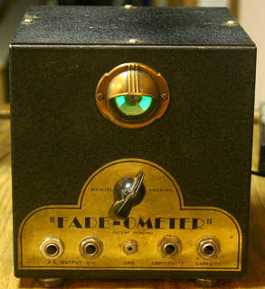
On the right is a device called a Fade-Ometer. Besides being manufactured in Portland, Oregon, I have not found any information on this piece yet. By definition, a fadeometer measures the fading characteristics of materials as a result of exposure to light. I don't think that's what this is for, so I'll keep looking for information on this device. |
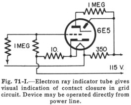 This diagram and the corresponding paragraph below describe a basic continuity tester using the eye.
Source: Figure 71-I shows a simple application of an electron indicator tube as a substitute for a buzzer, lamp, or meter to indicate when a contact is established between two metallic bodies where it is essential that the current through the contacts be kept small. In case, one of the contacts must be at ground potential, a grounded power line connection can not be used and an isolating transformer must be added. |
Source: With the a.g.c. systems included in present
TV sets, the picture contrast changes very little for large changes in input signal.
Therefore, it is difficult to adjust indoor antennas, outside rotating beams, or TV
boosters for best results. This magic-eye probecan be used when you want maximum
input signal. The probe consists of an electron ray-indicator tube. The choice
of tube is not critical. You can use any of the types mentioned in the circuit
diagram (Figure 818). To build the probe, obtain a section of tubing having a length
of about 4˝ inches, and a diameter of 1˝ inches, approximately. The tubing can be
plastic, bakelite, aluminum, or any material you have on hand. The indicating face
of the magic-eye tube should extend slightly from one end of the probe housing while the
probe tip is mounted at the other end. You will need to bring two leads into the
probe, one for B plus and the other for one leg of the filament line. These voltages
can be obtained quite readily from the TV set you are working on. The two wires,
filament and B plus, should terminate in shielded alligator clips which can then be
attached to the desired filament and B plus voltage points in the TV set. |
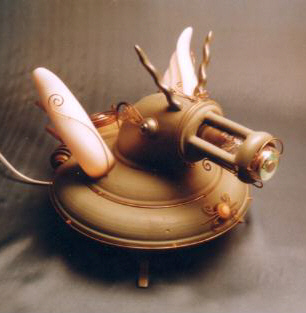
Since the introduction of the magic eye tube, there seems to have been a continuous desire among hobbyists and inventors to incorporate the use the magic eye tube in their projects and creations. Whether actually functional, or just as an attention getter, that desire continues among tube enthusiasts today.
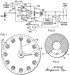
The picture on the left contains images from a patent filed by Benjamin Fox in 1946. He cites that his invention relates to artistic or novelty display devices, and in one case, a clock. His designs emphasize use of the magic eye tube as the luminous display. |
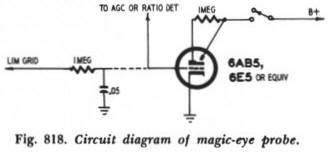 The selection below describes the construction of a probe
using a magic eye tube.
The selection below describes the construction of a probe
using a magic eye tube.